


Power generation facilities operate under conditions that leave very little margin for error. When a turbine trips unexpectedly or a startup sequence does not proceed as planned, the system must redirect high-pressure, high-temperature steam quickly and safely. The equipment responsible for managing that transition is not always visible in facility discussions, but its performance directly determines whether a plant recovers cleanly or sustains damage to downstream equipment. Understanding what separates adequate valve solutions from genuinely reliable ones is relevant to engineers, procurement specialists, and plant managers who are accountable for uptime and operational continuity.
The decisions made around steam management equipment tend to reflect broader values within an organization: how risk is calculated, how much weight is placed on long-term reliability versus initial cost, and how familiar the procurement team is with the technical demands of the application. This article examines how industrial-grade turbine bypass valve solutions are designed, what conditions they must withstand, and what operational factors distinguish dependable equipment from components that perform adequately only under ideal conditions.
What a Turbine Bypass Valve Actually Does in a Live System
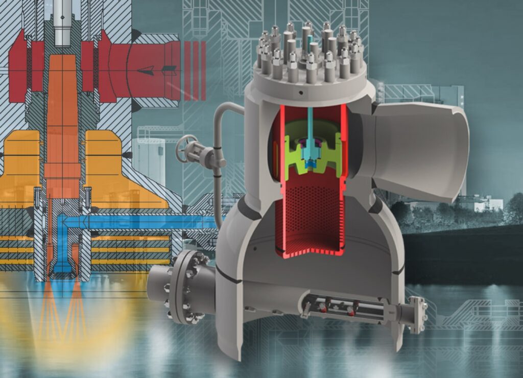
A turbine bypass valve is a pressure control and steam routing device installed in power plants to divert steam away from the turbine during startup, shutdown, or trip conditions. Rather than allowing excess or uncontrolled steam to accumulate or cause pressure surges within the system, the valve redirects flow to a condenser or other designated pathway. This function protects both the turbine and the broader thermal system from conditions that could cause mechanical stress or equipment failure. For a more detailed Turbine Bypass Valve overview, including the range of configurations available for different plant architectures, the relevant product category provides structured technical context.
The role of this valve is not passive. It must respond to rapid changes in system pressure, control steam flow with precision under varying thermal loads, and maintain a reliable seal when closed. These requirements are simultaneous and non-negotiable in an operating plant. A valve that handles one condition well but fails under another creates vulnerabilities that may not surface until a critical moment.
The Pressure and Temperature Environment These Valves Must Survive
Steam conditions inside a power plant during bypass operation are among the most demanding that any valve will encounter in industrial service. The steam passing through a turbine bypass valve during a turbine trip or a controlled startup carries both high pressure and high thermal energy. When a valve opens under those conditions, it experiences rapid changes in mechanical stress, thermal expansion, and flow velocity simultaneously.
Industrial-grade valve bodies, seats, and trim components must be selected and manufactured with those combined stresses in mind. A valve that is rated appropriately for pressure alone, without accounting for thermal cycling and flow-induced vibration, may perform reliably during initial commissioning and begin to degrade as real-world operating cycles accumulate. This is where material selection, precision machining tolerances, and design intent become visible in actual plant performance rather than only in a specification document.
Response Time as an Operational Requirement, Not a Feature
When a turbine trips, the bypass valve must respond within a very short window to prevent steam pressure from exceeding safe thresholds. This is not a desirable characteristic — it is a functional requirement of the application. A slow-acting valve, even one that eventually reaches full open position, allows pressure to build in a way that stresses associated pipework, joints, and turbine components.
Response time in a turbine bypass valve is shaped by actuator design, control signal integration, and internal valve geometry. Each of these elements must be matched to the specific system it serves. A valve sourced without reference to the actual control system architecture or the expected trip scenarios is unlikely to behave consistently across all operating conditions, regardless of what its documentation states.
Design Factors That Separate Industrial-Grade Equipment from Standard Alternatives
The distinction between a standard control valve and an industrial-grade turbine bypass valve is not purely a matter of pressure class or material grade. It reflects how the valve is designed to behave across a full range of operating states, including the transitions between states. Most plant valve failures occur not during steady-state operation but during transient events — startup sequences, load changes, and emergency trips. Industrial-grade solutions are engineered with those transitions as the primary design condition, not as a secondary consideration.
This approach affects nearly every aspect of valve construction. Seat geometry must handle partial flow conditions without erosion from high-velocity steam. Packing arrangements must accommodate thermal cycling without developing leakage paths. Actuator sizing must ensure that available control air or hydraulic pressure is sufficient to open or close the valve against system pressure at the exact moment it is needed.
Noise and Vibration as Engineering Problems, Not Inconveniences
High-pressure steam passing through a partially open valve generates significant aerodynamic noise and flow-induced vibration. In standard valve applications, this may be a nuisance that requires acoustic lagging or pipe support modifications. In a turbine bypass application, it is an engineering problem with direct consequences for valve longevity and structural integrity. Excessive vibration at the valve body can fatigue connections, loosen packing, and accelerate seat wear in ways that are difficult to detect during routine inspection intervals.
Industrial-grade turbine bypass valve designs address this through trim staging, which breaks steam pressure reduction into multiple controlled steps rather than allowing it to occur across a single restriction point. This approach, supported by internationally recognized standards for industrial valve design, reduces the acoustic energy generated during partial-load conditions and extends the service life of internal components. Plants that specify trim staging appropriately for their steam conditions generally see longer intervals between maintenance events and more consistent valve behavior over time.
Actuator and Controls Integration in High-Demand Applications
A turbine bypass valve does not function in isolation. It operates as part of a coordinated system that includes distributed control systems, pressure transmitters, trip logic, and often additional protective interlocks. The valve’s actuator must be compatible with the control signals it receives, capable of the required stroking speed, and mechanically reliable enough to operate correctly after extended standby periods.
This last point is frequently underestimated in procurement decisions. A valve that sits in standby position for weeks between turbine trips must still open correctly the first time it receives a signal. Actuators that develop internal friction, seals that degrade during inactivity, or positioners that drift during long hold periods all contribute to the risk of a failed response exactly when the system needs the valve to act. Industrial-grade solutions address standby reliability as a specific engineering requirement rather than assuming that inactivity presents no risk.
Maintenance Expectations and Long-Term Operating Costs
The total cost of a turbine bypass valve is not defined by its purchase price. It is defined by the maintenance intervals it requires, the impact of unplanned outages when it fails, and the extent to which its design allows for inspection and repair without full removal from the line. These factors matter more to plant maintenance engineers than initial specifications, yet they are often not fully evaluated during the procurement process.
Industrial-grade designs typically allow for in-line maintenance of key components, including seat and trim replacement, without requiring complete valve removal and pipe flange separation. This reduces the labor cost and outage duration associated with maintenance events. It also means that maintenance can be scheduled and controlled rather than performed reactively under time pressure during an unplanned shutdown.
Inspection Intervals and Wear Pattern Predictability
Well-designed turbine bypass valves exhibit wear patterns that are predictable and consistent across operating cycles. Engineers responsible for maintenance planning can use historical data from similar installations to anticipate when trim components will need replacement, what inspection criteria to apply, and how operating conditions affect wear rates. This predictability is not incidental — it is a product of consistent internal geometry, appropriate material selection, and controlled manufacturing tolerances.
Valves that show unpredictable wear patterns, or that require unscheduled intervention after relatively few operating cycles, indicate either a mismatch between valve design and application conditions or inconsistencies in manufacturing quality. Both scenarios increase operating cost and create planning uncertainty that compounds over the service life of the installation.
Specification and Selection: Where Decisions Have Lasting Consequences
Selecting a turbine bypass valve for a specific plant application requires input from multiple disciplines. The process and mechanical conditions define the pressure, temperature, and flow requirements. The control system architecture defines the actuator interface and response requirements. The maintenance program defines the access and in-service repair expectations. No single team owns all of these inputs, and valve selection decisions made without coordinating across them tend to produce equipment that performs acceptably in only some of the conditions it will encounter.
Plants that invest time in defining their full operating envelope — including startup sequences, trip scenarios, and expected maintenance intervals — before specifying a turbine bypass valve consistently see better long-term outcomes than those that prioritize speed of procurement or lowest initial cost. The valve is a long-cycle asset. Decisions made at the point of specification remain consequential for the full duration of its service life.
Closing Observations
Turbine bypass valves occupy a critical position in power plant operations, yet they are often evaluated with less rigor than other major plant components. The consequences of that underestimation are not always immediate, but they become apparent over time in the form of maintenance demands, unplanned outages, and control system reliability concerns.
What distinguishes industrial-grade solutions is not a single design feature or material specification. It is the extent to which the entire valve system — body, trim, actuator, and controls interface — has been engineered with the real operating environment in mind. That includes transient conditions, standby periods, thermal cycling, and the practical realities of maintenance access in an operating plant.
For procurement teams, plant engineers, and reliability managers, understanding what to look for in a turbine bypass valve is the first step toward making a selection that holds up not just at commissioning but across years of demanding service. The investment in that understanding is modest relative to the cost of getting it wrong.